Snap4city enables you to quickly deploy smart city applications by accessing real time data from thousands of real sensors located in several cities. In a previous article, we saw how we can expand the Snap4city network by adding our own IOT sensor using a Raspberry Pi.
Single board computers like the RPi are great for this task and can offer us lots of flexibility. That said, in most scenarios a simpler device will work as efficiently, with the advantage of the reduction of costs, lower energy consumption and a simpler deploying workflow.
The ESP8266 family of devices made its appearance more than a decade ago, virtually marking the beginning of the DIY-IOT era. They are really inexpensive, can be easily programmed with commonly available software tools like the Arduino IDE, and give hackers out-of-the-box WIFI capabilities.
In this tutorial, we will go through the steps required to connect an ESP-12 device to the snap4city network and upload the readings of a temperature and humidity sensor.
An IOT application on the snap4city platform will be used to output the real time sensor values to a public dashboard.
Before getting to it, let’s review the hardware we will need:

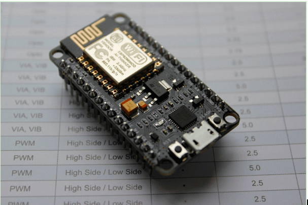
Img: An ESP12 development module. Image by Vowstar CC BY-SA 4.0, from Wikimedia Commons
- An ESP-12 based device or, to be technically accurate an “ESP-12 Development Module”. They can be easily found under several names like:
- NodeMcu V1.0, LoLin V3 NodeMcu Board, Wemos D1, etc.
- A DHT11 or DHT22 temperature-humidity digital sensor.
- A USB →micro USB-B cable.
- Some female jumper wires
Registering your device on snap4city
In order to add a custom device to the snap4city, firstly we need to register it on the platform. To do so, you need an account with a permission level of Manager or higher. If you still don’t have an account go ahead and create one by clicking on the new registration link on the home page.
Let’s proceed to the registration of a new device. After logging in, go to IOT directory and devices > My IOT devices > Add new device.
Give your device a name. In this tutorial I’ll call it codemotion_tutorial_ESP12. Choose the location where it will be placed on the map. For the device model, choose Arduino UNO. Copy the device name and both keys and keep them for later use (you will need them to access to the data from your device) and, finally, click on submit device.
Go to My IOT devices: you will notice that snap4city has already created two sensor devices for you, with temperature and humidity as value types. Click on the [+] button to see all device’s properties.

Img: Registered IOT devices.
Configuring the Arduino IDE
The ESP-12 is a WIFI capable microcontroller. In order for it to work, we have to program it. This process usually involves compiling code and sending the program using dedicated hardware that is normally attached to a serial port on your PC: the programmer, or burner. Luckily for us, gathering all these elements is as simple as downloading the Arduino IDE, some dependencies and attaching the ESP-12 device to our PC using the USB cable.
First, we have to add this device to the list of available boards within the IDE. Open File > Preferences and paste the following URL on the Additional Boards Manager URLs
http://arduino.esp8266.com/stable/package_esp8266com_index.json
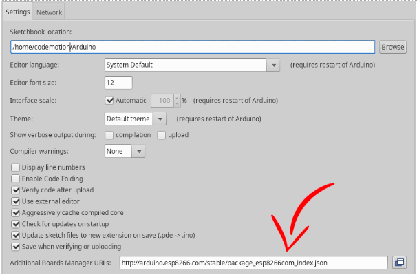
Img: Arduino IDE preferences dialog.
Then go to Tools > Board > Boards manager.
Search the package esp8266 by ESP8266 Community and install it.
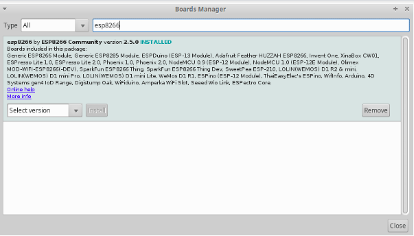
Img: Arduino IDE Boards Manager
Now you can go to Tools > Board and select your model from the list. If your manufacturer is not listed, choosing nodeMCU 1.0 will work most of the times.
Plug the board to your computer and choose the port to use on Tools > Port. Most of the time you will only have one option here, if you are on a windows PC it will be called COM# while on linux or mac it should begin with /dev.
To complete the configuration we just need one last thing: the library required to work with the DHT sensor.
Go to Sketch > Include library > Manage Libraries. Search for the DHT sensor library for ESPx by beegee_tokyo and install it.

Img: Arduino IDE Library Manager
Wiring the ESP-12 and the DHT11/DHT22
Follow the scheme below to connect your sensor to the board.
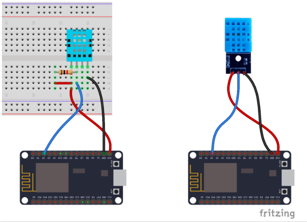
Img: Wiring the ESP-12 and the DHT11/DHT22 sensor.
Notice that the DHT-22 and DHT-11 sensor might come with three or four exposed pins. If you have the four pins version, you will need to add a pull-up resistor between the data and power lines. Values between 4.7Kohms and 10Kohms will work.
Programming the device.
The expected behaviour is quite simple:
- Connect to a WIFI network and check whatever the internet connection is working.
- Read the DHT11/DHT22 sensor
- Format the payload according to the NGSIv1 API
- Send a POST request to the server
- Wait and repeat from #2.
Here’s a simple sketch doing just that. Download, unzip it and open the following file with the arduino IDE.
tut02_ESP/snap4city_device/snap4citu_device.ino
Or if you have Git installed you can just:
git clone https://gitlab.com/daylanKifky/codemotion_snap4city_tutorial.git
cd codemotion_snap4city_tutorial/
arduino tut02_ESP/snap4city_device/snap4citu_device.ino
The code is pretty much self-explanatory. If you have some programming experience, you will be able to easily spot the described steps. If not don’t worry, you just have to make sure to fill some placeholder strings with the correct data:
Your WIFI credentials:
#define STASSID "<< YOUR WIFI SSID >>" // <--- Set your WIFI's name
#define STAPSK "<< YOUR WIFI PASSWORD >>" // <--- Set your WIFI's password
And the NameID and Keys from the device we registered on the snap4city platform:
// !!! --------- Set your device attributes ------- !!!
// They were created during registration on the snap4city platform
#define S4C_DEVICE_ID "<< YOUR DEVICE NAME ID >>"
#define S4C_K1 "<< YOUR DEVICE KEY 1 >>"
#define S4C_K2 "<< YOUR DEVICE KEY 2 >>"
Now you can go ahead and press the Upload button on the top-left of the arduino IDE. It will compile the code and send the program to the ESP-12.
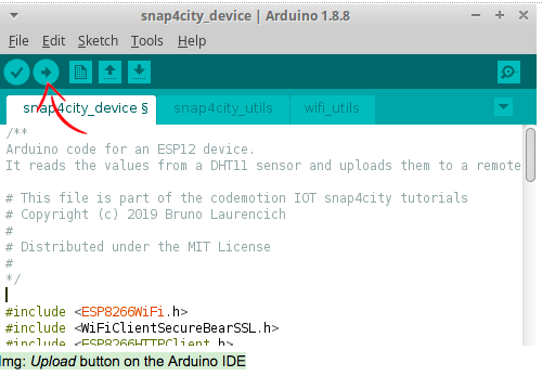
Img: Upload button on the Arduino IDE
Hint:
When running on a linux machine you might get an error like:
An error occurred while uploading the sketch
error: cannot access /dev/ttyUSB0
This just means that your user doesn’t have the permissions to write to the USB port. A temporary workaround is:
sudo chmod a+x /dev/ttyUSB0
(of course you should use the name of your USB device instead of /dev/ttyUSB0)
Or you can add your user to the dialout group to get permanent permissions:
sudo usermod -a -G dialout $USER
Once the ESP-12 is programmed, it will start doing its job immediately.
Let’s double-check everything is working properly: open a serial console by clicking on the Serial Monitor button on the top-right. Set the baudrate (on the bottom-right of the console) to match the value we used on the sketch, in this case 115200.
If you see an output like the one in the image below then everything went right, and the ESP-12 is already uploading values to the broker.
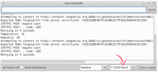
Img: Arduino IDE Serial Monitor
If there’s any error, or if you want to get a more verbose output, try setting the following line to true and Upload the code again.
#define PRINT_BROKER_RESPONSE false
Creating the Dashboard on snap4city
The workflow on snap4city usually involves creating a dashboard, which is a public or private interactive page where a user can see and sometimes modify the data that’s available through the platform.
After logging in, click on My Dashboards in my Organization > New Dashboard. Give it a meaningful name (if you decide to make it public, this name will be seen by others), choose the empty dashboard template and click next. On the second screen, click on the big Instantiation button to proceed.
We will manage the dashboard from an underlying IOT application, so let’s create one. Go to IOT applications > Create new. Give it a name and choose the type basic. You will see your recently created application on the list. By clicking it you will access to the development environment within snap4city: the nodeRed GUI.
If you are not familiar with nodeRed: it is a flow-based visual programming language that will allow us to easily create IOT applications by connecting nodes with wires and then deploying them.
A group of connected nodes is called a flow. We will create a simple one to monitor the changes on the temperature value of our sensor and display it using a widget on our dashboard.
Let’s start by adding our first node. You will see list of all the available ones on the left. On top of the list there’s a search bar: look for the fiware-orion-in node and drag it to the working area.
Double click on the node to edit its parameters, in this case add the following:
- Device type: Ambiental
- Device NameID: <The name of your registered device>
- Key1: <The key1 of your registered device>
- Key2: <The key2 of your registered device>
- Service: add a new orion service
- URL: broker1.snap4city.org
- Port: 8080
- Name: orionUNIFI
Now place a function node. It will allow us to modify the incoming values with a piece of arbitrary javascript code. Paste the following lines:
let temp;
msg.payload[0].attributes.some(function(attr_obj){
if (attr_obj.name === "temperature"){
temp = attr_obj.value;
return true;
}
return false;
});
msg.payload = temp;
return msg;
As you can see, we are traversing the incoming array and just retaining the value of the object which has a “name” property equal to “temperature”. We then put that value on msg.payload, which is the default practice within nodeRed.
The output of the function node should be wired to:
- A debug node that will allow us to see the changes directly on the debug console, on the right side of the nodeRed GUI.
- A single-content node that will create a widget on one of our dashboards. Once placed on the working area, double-click it and choose the name of your dashboard from the dropdown menu. You can also click on the view dashboard button before confirming your edits to see the result on another tab.
The resulting flow should look like this:

Img: nodeRed flow: monitoring changes on the registered sensor values and displaying them on the dashboard.
Deploy your flow by clicking on the top-right button. You should now see a widget on your dashboard. Test the sensor by putting it next to a warm object (the hot air coming out from your laptop is ideal for this task). The values on both the nodeRed debug console and your dashboard should change to reflect the new temperature.
Img: The dashboard displaying the real time values on the registered sensor.

Going Further
As you can see snap4city gives you a reliable and flexible infrastructure to deploy any type of IOT projects combining publicly available datasets with your own devices.
Apart from the ESP-12 that we covered here, you can use a Raspberry Pi, or many other networking capable devices, making the creation of your custom IOT fleet a simple and inexpensive process.
You can find the sources for this tutorial here.
Snap4City Hack
Snap4City platforms and solutions are available at Snap4city.org website, where you can register and start exploring its features. But if you want to really challenge your skills and propose your innovative solutions for connected cities, you can join the upcoming Snap4City Hack, the big online hackathon on the topics of Smart City and IoT.
Snap4City launched a big online Hackathon on Ecological Watch, Social and Service Evolution, Stimulating Business Growth, City Aware.
Using Snap4City tools to manage IoT, Big Data and analytics, the hackathon challenges will cover different themes – Ecological Watch, Social and Service Evolution, Stimulating Business Growth, City Aware – and real data from cities such as Helsinki or Antwerp.
Further information on the Hackathon is available on the on Snap4City.org/hackathon website.
